The 3D Canvas object is a container for 3D objects and rendering of a 3D world.
3D objects, in the form of triangle meshes, are placed in a 3D space. The 3D objects are either loaded from external files or selected from any of the internally available predefined meshes. A virtual camera is observing the 3D space through a virtual lens and renders a projection of the 3D scene in the canvas on the screen.
The 3D Canvas can be used to create scenes with a greater feeling of depth and 3D space than just a flat 2D surface. By using the 3D Canvas in combination with the Composition functionality of the 2D objects you can achieve a far more compelling look for presenting your real-time motion graphics. 3D objects can place graphics from compositions onto their surface by the use of custom 3D object materials.
When you first add a new 3D Canvas to a layer it will not contain anything and only an empty surface is displayed on the screen. You need to add 3D objects to the 3D canvas before anything will be displayed.
Add new objects to the canvas by clicking on the arrow below the Canvas 3D button in the Insert tab on the tool bar or by right-clicking the 3D Canvas object in the project tree. You can either add own 3D mesh objects from a file or you can use one of the built-in objects such as the cube, plane, sphere, cylinder and cone. Importing objects from file require that you have exported your 3D objects from your 3D modelling software in one of the following file formats:
- Autodesk FBX (*.fbx)
- AutoCAD DXF (*.dxf)
- Collada DAE (*.dae)
- Alias OBJ (*.obj)
- 3D Studio 3DS (*.3ds)
Objects can also be stored in a compressed zip file.
Placement and rotations of the 3D objects is done by going into 3D editing mode in the Screen View. Enter 3D mode by selecting the 3D Canvas and in its context menu select Edit. The edit mode can also be entered with the F2 short-cut key. Exit 3D mode by either clicking the Exit 3D mode button on the tool bar or by pressing the Tab key on your keyboard. If you have previously entered 3D mode for a 3D Canvas you can toggle between 3D and 2D mode with the Tab key.
The 3D Canvas renders its contents from the view of a virtual camera. In 3D editing mode you may however freely move around in the 3D space without affecting the camera rendering view. As soon as you start navigating in the 3D space it will switch over to a free movement camera for observing the 3D space from other angles. The view is rotated by holding down the right mouse button in the Screen View and moving the mouse left/right to change heading and up/down to pitch. You move around in the world by clicking the middle mouse button and move the mouse. Zoom in and out with the mouse scroll wheel.
The virtual camera that is used for rendering the 3D world in 2D mode can be placed and oriented freely. The easiest way of placing and orienting the camera is by using the free view in 3D mode and navigate to a spot and view that you wish the camera to see. You can then align the virtual camera with the current view by selecting the Camera in the project tree and use the Align Camera With View option in its context menu.
If you want to align the current view with what the camera is seeing you can use the drop-down menu below the Screen View, that says "Free" when you have moved around, to switch back to the Camera view. As soon as you start moving around in the view again it will automatically switch back to the free view mode without affecting the camera.
3D objects that are loaded or added to the 3D canvas get their default material that was defined in the 3D modelling software. For the built-in object types this is just a white material without any texture. You may however override all loaded materials by editing the properties of each of the materials that appear in the project tree under the loaded object. If your object is correctly UV-mapped from your 3D modelling software you may assign images to use as a texture on the object. If your 3D object contains normal vectors for its faces you may also use the environment map option to add either a MatCap texture that contains the lighting and material properties as a spherical texture or you may use the environment texture as a reflection map on the object to make it appear more like metal.
Instead of using image files as material textures you may also use other compositions that you have created within the 2D editing mode. This makes it possible to transform any of the 2D objects you place in the 2D mode into the 3D world. If you for example want to display a text in 3D you can add a 2D text object to your layer and place it as a child to a Composition object. Change the composition's Blending mode to HiddenComposition and give it a name in the properties. Doing these two property changes to a composition object makes it available for selection as a 3D object material texture. To place the text in the 3D world you can now add a 3D plane object and change its material texture to reference the composition. This is done by clicking the ... button that appears when you give focus to the Texture property in a material. In the dialog that appears you can now click the Select Composition button and a menu appears where you can select your previously created composition.
When using compositions as material textures it is necessary to add a separate Composition object in the 2D mode to group together other 2D objects that you want to use as a texture on a 3D object. This is especially true when you for example want to place small texts on bigger 3D object surfaces. Then you may need to create a bigger Composition object to hold your small text object just to get the image dimensions right for your texture mapped object.
Normal mapping is a technique that is used for faking the lighting of bumps and dents. It is used to add detail to 3D objects without adding more polygons. This is achieved by using a normal map texture that affect the light calculation of each pixel drawn on the screen. Normal maps can also be used to affect reflections from environment maps in Demorize.
A normal map is a special kind of texture that encodes the relative change of the surface normal vectors in the R, G and B channels of the image. Normal maps typically have a bluish look to them due to the encoding schema used, as seen in the below normal map example image.
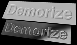
When a normal map is assigned to a flat 3D surface and a light source is placed in the scene, the surface will look like it has bumped details. The same is true when an environment map is applied. These two scenarios are shown in the below figure where the top plane is just using the above normal map for its light calculations while the bottom plane has a reflection environment map applied to it.
Normal maps can be created in real-time by Demorize. This is done by using a Composition object and adding a filter named "Normal Map" to it. By doing so everything that is rendered in the composition will be transformed into a normal map using the filter settings to define how much bumpiness that shall be created in the normal map. By for example adding text objects to the composition you can create bumped text that can be used on 3D geometry like the examples above.